Thursday, 3 May 2012

Sound Editing


Sound Editing
Once the animation had rendered, it was time to add the sound. Although this was not a requirement of the specification, I felt that it would just be a nice touch.
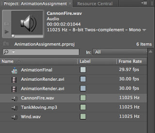
Using Adobe Premiere to add the sound was very simple. The software is very easy to pick up, with the hardest part deciding what formats to use for the output. Once opening the software, the animation render was imported. It appeared in the top left-hand corner of the window and then it was just a case of dragging and dropping it into the timeline at the bottom of the screen.
The sound clips were imported in the same fashion and dragged and dropped onto the audio timeline below the video output. It was then a case of matching the sounds to the animation. This was done easily by dragging the sound clips along the timeline, clipping or extending them. Throughout the process you are able to see the animation in the top right-hand corner of the window to make the overlay of sound easy to see.
And that was that, 12 weeks and one animation complete with sound effects!

Monday, 30 April 2012

Rendering


Having completed the animation, including tweaking the various aspects, as explained previously, it was time to render it. Fortunately this was a relatively simple process once the required output format had been chosen. The only aspect to watch out for was the file location.

Once you are on the rendering options panel, it is easy to just see the big ‘Render’ button a press that straight away. This will, of course, render the animation but once the render has completed you will be dismayed to learn that it has not been saved on the computer.
Before the render button is clicked it is important to specify a file path in which the final render is to be saved. This is done my scrolling down the rendering setup menu to the output section. Within this section is a default file path, the one that will not be saved on the computer. To edit this, the ‘file’ button was pressed and then the desired file path was created.
Once this had been done, the render was initiated.

Timeline Adjustments


More of an oversight than a necessary part of the project, when the whole animation was complete I realised that the whole thing was spread over just 100 frames. This created a problem in that when it was played, if you blinked you would miss it. Of course after spending so much time with the clip, this was not a desirable outcome.
To rectify the problem, the timeline editor was used to extend the frame count to 1800. This frame number was chosen because this would make the animation a total of a minute at a run-time of 30 frames-per-second. Unfortunately this did not automatically reposition the key frames within the timeline.
Because the key frames were not automatically moved with the timeline lengthening, this had to be done manually. To do this was just a case of clicking on the key frames in the timeline and dragging them to the appropriate position. Of course some simple calculations had to be done to make sure that the key frames were being moved to the correct position. This was a largely problem-free procedure with the exception of having to fine tune some of the key frame placements so that the animation played out as intended with regards to the camera position in relation to the model movements.

The Great Blue Beyond


Having laid out the majority of the animation, I realised that as the Ornithopter soars through the air, it is, in fact, placed against the rather dreary grey default background of the 3DS Max environment. I felt that this was not realistic and also would not do justice to the wonderful flying machine invention of the great Leonardo Da Vinci.
Rather than flying through the grey expanse of emptiness I decided to place the winged machine into the great blue beyond, where it belongs.
Initially I had planned to just include the sky in such a way that it would not surround the entire environment but could be seen from the camera. However, due to the panning of the camera, the entire environment had to be surrounded.
To achieve the necessary effect, I placed planes against all four edges of the bottom, ground plane so as to create a box with the roof missing. It then became a matter of texturing these planes with the brilliant blue of a clear sky. This was just an image from the internet as it was felt that simply colouring the planes in would not achieve the subtle contrasts of a real sky backdrop.
Once the blue backdrop was in place, the lighting needed to be put into place. This was achieved by the inclusion of omnilights. Originally, it was felt that a single light would be sufficient, however when this was put into the scene it was discovered that no matter where it was placed one of the sky planes became completely black, as if in shadow. Of course this was not acceptable.
To solve the problem, one light was placed in the centre of the scene, serving as the main light source and then a second to illuminate the shaded sky panel. These lights provided a nice light source for the scene with the models casting the appropriate shadows.

Invisible Cannon Balls


Whilst doing the camera orientation I came across a different problem. The cannon balls were, as I mentioned before, present throughout the animation, hovering in mid-air. This became a problem because the camera would see them before the tank arrived to cover them up. This meant that I had two options. I could either make the cannon balls move with the tank from the start of the animation or make the cannon balls invisible until they were needed. I decided to do the latter and edit the animation so that the cannon balls could not be seen until they were fired from the cannons.
To achieve this, I employed the wonders of the Auto Key tool. From the start of the animation I created a key frame and edited the cannon ball Object Properties to make them invisible. I then added another Key Frame just before the cannon balls were about to fire to make them  visible again.
This meant that the camera would not see the cannon balls until they were fired from the cannons and hit the targets.

As a side note, I had tried to modify their visibility using the Set Key tool however editing the visibility through this method did not change the animation. They were either visible of not throughout the whole animation regardless of me putting in key frames to change this.
I’m glad to say, problem solved!

Camera Path


Once the basic movement was finished, the camera was then added and positioned so that it recorded the action. Using the storyboard I had created earlier in the project as a guideline, I created a line that was to become the path that the camera would follow through the animation.
Initially I mapped out the path on a flat plane and the edited the line to incorporate the height variations that needed to be added. The camera was then added, ctrl + C, and constrained to this path. As with the models previously, the camera did not change its angle as it moved along the path. This issue was not as easy to fix as before (by clicking the follow box) as I needed to change its angle at various points along the path to focus on the relevant model.
This was accomplished by using the Set Key function to change the orientation of the camera throughout the various frames of the animation. Although, in itself, this task was not technically challenging, it was time consuming as I had to go through the entire animation, mostly frame by frame, editing the camera orientation.
This allowed me to fine tune the camera angles for the whole animation.

Target Impacts


After I had lined the cannon balls up so they actually went through the straw men, I then had to animate the straw men being hit and being knocked aside by the cannon ball.
Initially I wanted to use the Reactor for this effect but found that it was very difficult to get all the cannon balls hitting the straw men accurately. Instead I chose to manually animate them using the Set Key tool.
I went through the timeline to see the exact frame at which the cannon balls hit each target and started their motion from this point. Depending upon where they were hit I rotated and flipped the straw men accordingly.
This was more challenging than I initially thought as I had to guess how far back they would be moved by the force of the impact. Also, as I had wanted to make each cannon fire at slightly different times and the cannon balls move at various paces (reflecting inaccuracies in cannon technology) the animation of each straw man had to be tailored to their own specific impact.
Additionally, once doing the impacts I realised that that cannon balls stopped in mid-air which was not awfully realistic. This was rectified by adding in some key frames using the Set Key tool to make the ground their ending position.

Tuesday, 24 April 2012

The Cannon Balls

In order for any tank to be effective (bar squashing things) it must have weapons, in this case cannon balls. I decided to place the cannon balls in position from the start of the animation, save having to move them with the tank. In a later blog I will describe how I made them invisible until they were needed.
To position the cannon balls effectively, I moved up the tank to the point where it is about to fire.
I then created the cannon balls from basic sphere shapes and textured them in the same way previously explained.
I then moved them into the cannon mouth so they appear to be coming from within them when the tank fires.
Then came the task of animating them so that they actually hit their intended targets. To do this I drew in some simple lines from the positioned straw men back to the tank, this gave me an idea of which can should fire at which target. This allowed me to also fine tune the cannon balls' initial position within the cannon.
I then used the Set Key tool to move the cannon balls to their targets and then to land on the floor.
Simple but effective.

The Targets

As part of the animation some poor, defenceless straw men are brutally attacked by the marauding Armoured Tank.
In order to position the victims I first imported the straw man model into the animation file.
I then drew a circle at the end of the tanks' path, where I wanted the assault to happen. It was then case of locking the straw man to this circular path and then used the same technique as I did for duplicating the cannons around the tank to create the ring of straw men.
Of course the tank has to be able drive into this ring. Because of the manner in which I had created this group there was not enough room for the tank to enter without passing through a straw man or two, which of course would shatter the illusion of reality.

Fortunately this problem was easily rectified by simple using the select and move tool to reposition the obstructing straw men into a more suitable position.

The Basic Movement

The foundation of the animation is, of course, the movement within it. Having described previously constraining the models to a set path, they would then move along these paths from the first frame to the end, at this point it was just 1 to 100.
At first they simply moved along the path in a fixed position. Due to the conical shape of the tank it was not so much of a problem but with the Ornithopter it did not look right, at some point it was flying sideways and then backwards! To fix this problem I positioned the models along the paths and checked the follow option in the editor. From now on they would now follow their respective paths facing ion the correct direction.

Tuesday, 20 March 2012

The Animation So Far

I have started messing about with my final animation, I haven't got very far but here it is at the moment.
I started by importing my three models into a single file. This was relatively simple except that they lost their textures. Slightly irritating but not the end of the world, I reapplied them and was back on track.
I then decided to create my Ornithopter flight path and then lock the Ornithopter model to it. Here came the second problem, up to this point the models were essentially just various shapes positioned to look like they're intended invention. This meant that each individual part could be moved independantly, the problem came when I tried to map the Ornithopter to its flight path. Rather than all the pieces moving and staying in their original orientation, each one was mapped to the start of the flight path, reducing my Ornithoper to looking like it had been in a serious collision, wings, wood and rope all bundled up together.
This made me realise that I needed to make all the individual pieces one whole model so they would be easier to work with. I did theis by selecting all the individual pieces of a model and, in the group menu, group them together!
This now meant that when I click on any part of a model, the whole thin is selected as if it was on object. I then mapped the Ornithopter to its flight path again, changed it's orientation to match the direction it will need to go and that was that. Jan 1, 3DS Max 0!

Reactor

Enter the world of real world physics! Within this tutorial we had a look at some of the applications of the built-in physics engine of 3DS Max.
We started with some basic models, a box falling onto another box, but then we were provided with some bowling alley models and had to use the physics engine to Reactor tool to make them behave appropriately.
Having been provided with the models we had to add them all to a Rigid Body Collection. We then had to give the models properties like Mass, Friction and Elasticity, these obviously dictate how these objects will behave in the simulation.
To make the animation work we had to start off the motion. This was the same procedure as we did for earlier basic animations, using AutoKey and moving the bowling ball. We only had to do this between zero and five frames, just to get it going. After that the physics takes over and moves the object how they would given their properties and motion.


SSSTTTTTEEEEEEEEERRRRRRRRIKE!!!!

The Walking Man

In this tutorial we had a look at some of the more natural, real-world pre-set actions, namely walking.
We started with a simple biped model, one of the model pre-sets. This model can be modified in itself but for this tutorial I left it as is.
This little animation was actually a lot easier than I thought it would be, the pre-set walking animation is great and gives a fantastic base to build on.
With any body part of the biped selected we just went into the motion tab and expanded the biped drop-down menu within. Here we select Footstep mode and then go down to the Footstep Creation menu below. This menu gives a few options for creating the footsteps that are required; these options include walking, running and jumping.
Although it is possible to create each footstep individually and position it, for this tutorial we used the Create Multiple Footsteps option. This panel gives you the option to create a path of as many footsteps that are needed, for this on I chose 12. When the selection is made, the footsteps are laid out in a straight line however the path can be bent by using the, appropriately named, bend option in the motion tab. I used this tool to make my biped walk in a circle.

Then it was just a matter of pressing play and watching the action…

Tuesday, 13 March 2012

Morpher

With this tutorial we worked with the Morpher tool. It was surprisingly easy to pick up.
We were provided with a face model which we then copied three times. To each of the three different faces a different effect was applied.
To do this we used the polygon selection, however, on the open mouth modification we coupled this with the Grow tool. We selected four of the polygons around the mouth, two on the bottom lip and two more within the mouth and then grew them around the mouth so the selected polygons coved the entirety of the bottom jaw. Then, using the move tool, we moved the jaw down, opening it.
A similar procedure was used to open the close the eyes and raise the eyebrows on the other two models. We were then left with three different, odd looking, faces.
Going back to the original face, the modifier tab was selected and the Morpher tool chosen. We were then presented with a list of blank channels. By right clicking on these channels we could then choose to add a morph from the scene. By repeating this process three times, one for each of the different morphs, the original face could now open its mouth, close its eyes and raise its eyebrows.
The final model was then TurboSmoothed and animated in the standard fashion. The only issue with the animation is that, on the timeline, all the channels are represented as a single line, each indistinguishable from the others. If we wanted to work with just one of the channels we could go into the curve editor and then choose just one to work on.
The morpher is very easy to use as long as proper labelling is used for each of the different morphs, just so they are easier to keep track of.


Pixar! Here we come!

Tuesday, 6 March 2012

The Storyboard

So here is the storyboard for my animation. Apologies for the poor drawing but hopefully the idea is put across.
The idea behind the animation is to show off the models in a realistic situation so I am aiming to get a few close up shots detailing the textures on the models.
I was working on the idea of a military weapons demonstration in Da Vinci's era focusing specifically on the Armoured Tank and it's destructive power.
In the opening scene, the Ornithopter will be seen flying through the sky, soaring in close to the camera and away again. The camera will then pan down to reveal the front of the Armoured Tank slowly moving into shot with the Ornithopter still flying above.
The straw man model will then be dropped from the flying machine which will be advanced upon by the Armoured Tank.
The tank will then fire a cannon ball at the straw man. The camera will zoom into the cannon ball spinning through the scene then zoom out as it impacts the straw man.
The tank will then be seen driving past the knocked down man and into a group of more straw man targets.
The final scene will show of all the tank's guns, flattening the group of targets with the words "Power through Innovation" appearing on the screen.
Time to get cracking!

Wednesday, 29 February 2012

The Straw Man

This was the simplest model that I produced. I started with some basic shapes, a sphere, capsule and four cylinders. For the arms I had to Bend them into place with the Bend modifier. The other shapes I just had to move them into place.
I then textured this base model using the UVW Map to fit the texture correctly. In order to add a bit of realism, I decided to add some straw sticking out from the body as a straw man would not be completely smooth. To do this I created cylinders with a very small radius and then clumped them together. I then placed these around the body of the model to create the illusion of loose bits of straw poking out of the body.


Third and final model finished!

Tuesday, 28 February 2012

The Ornithopter

The Ornithopter was Da Vinci's attempt to mimic the way that a bird moves it's wings to achieve the lift it needs to fly.
This model consists of basic shapes, fitted together like pieces of a jigsaw. The challenge with this model came when trying to add the wings.
For this I decided that the easiest thing to do would be to find a picture that I could use to create a texture that would match the wings, much like we did with the leaf tutorial detailed in earlier posts.
I found a suitable image and imported it into Photoshop. From here I cropped the image until I had the desired segment and then outlined the area I wanted and neatened it up by placing another layer underneath the original and creating a tight fit around the shape I wanted.

I then had the picture (texture) that I wanted and a black background with the exact outline of the image. I could then import the texture as normal into the material editor. Once I did this I had the wing set against a white background. In order to get rid of this I imported the cut-out image into the opacity section leaving just the wing texture.

Finally I created a plane and textured it with the wing image and positioned it.
Second model, finished.


The Tank

The tank started life as a two flattened cylinders and a couple of cones. Once the basic shape was established and put into place it was time to add the cannons.
This gave me a chance to use the lathing technique. Initially I drew out a 2D image in Illustrator as the base. This was a cross-section of half of the cannon. The lathing tool would be used to rotate this 2D image around a specified pivot point to create the final 3D model.
Once the image was imported into 3DS MAX I set about this process. First on the list was to edit the pivot point around which the image would be rotated. By default this is in the exact centre of the image, I learned that if this pivot is not moved before lathing, my cannon quickly resembled a candle stick. Not the desired result, as beutiful as it was. Having learnt from this mistake, I moved the pivot to the edge of the 2D image and then lathed it. I have a cannon!!
This was the point that I started to regret my choice of invention, I rememberered that Da Vinci's ingenius creation had a total of 36 of these cannons. Initially I thought that I would have to create 36 copies of my cannon model and then individually place them around the tank hull. :(
Snapshot to the rescue!! First I created a path for the cannon to follow, a circle, and placed it in the correct position. Next the cannon needed to be locked to that assigned path around the circumference of the tank. This was done by clicking the Animation tab, Constraints option then Path Constraints, I was then presented with an elastic band thingy which I attached to the path, I did have to reorientate the cannon a little as it defaulted to facing inwards.
Once the cannon was locked to the path, all I had to do was duplicate to cannon around this path. Snapshot did this wondefully. I just had to check the range box and then input how many copies I wanted.
Then came the wheels. A flattened cylinder to start with, I then converted it to an editable poly and deleted faces to create the spokes. Unfortunately, as the shapes are hollow, this meant that you could now see into the structure of the wheel. All I had to do here was to add some faces to cover these gaps.
I also added some lighting to this render. For this I needed to create a plane for the shadows to appear on. I then created a daylight system that mimics the conditions in Milan on a summer evening, romantic, I know!
Finally came the texturing, this was just a matter of finding suitable textures images on the internet and importing them into the Material Editor as bitmaps and then adding the images to the Bump section in order to give them a more realistic texture in the final render.


That was it, first model.....DONE!